Overview
Exosite provides built-in simulators for use in ExoSense applications. This post covers how to set up a CSV simulator, how to edit the CSV to simulate different data types, and how to get this simulated data displayed on a dashboard.
Getting the Simulator started
The Simulator Exosite provides is found in the IoT Marketplace through Murano. Follow the steps below to get the simulator added into your Murano instance:
- From Murano, under the IoT Connectors section, click on Create IoT Connector.
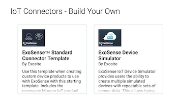
- Under the IoT Connectors - Build Your Own section, click on ExoSense Device Simulator.
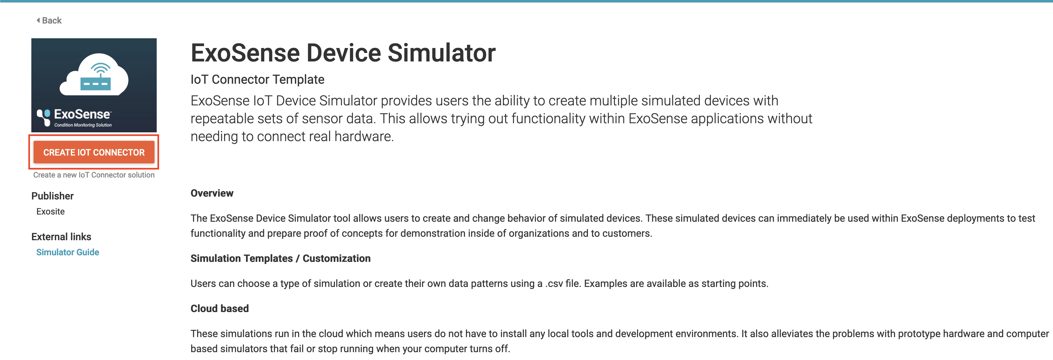
- In the ExoSense Device Simulator Overview, click on Create IoT Connector.
- Give your Simulator a name and then click Enable Solution.
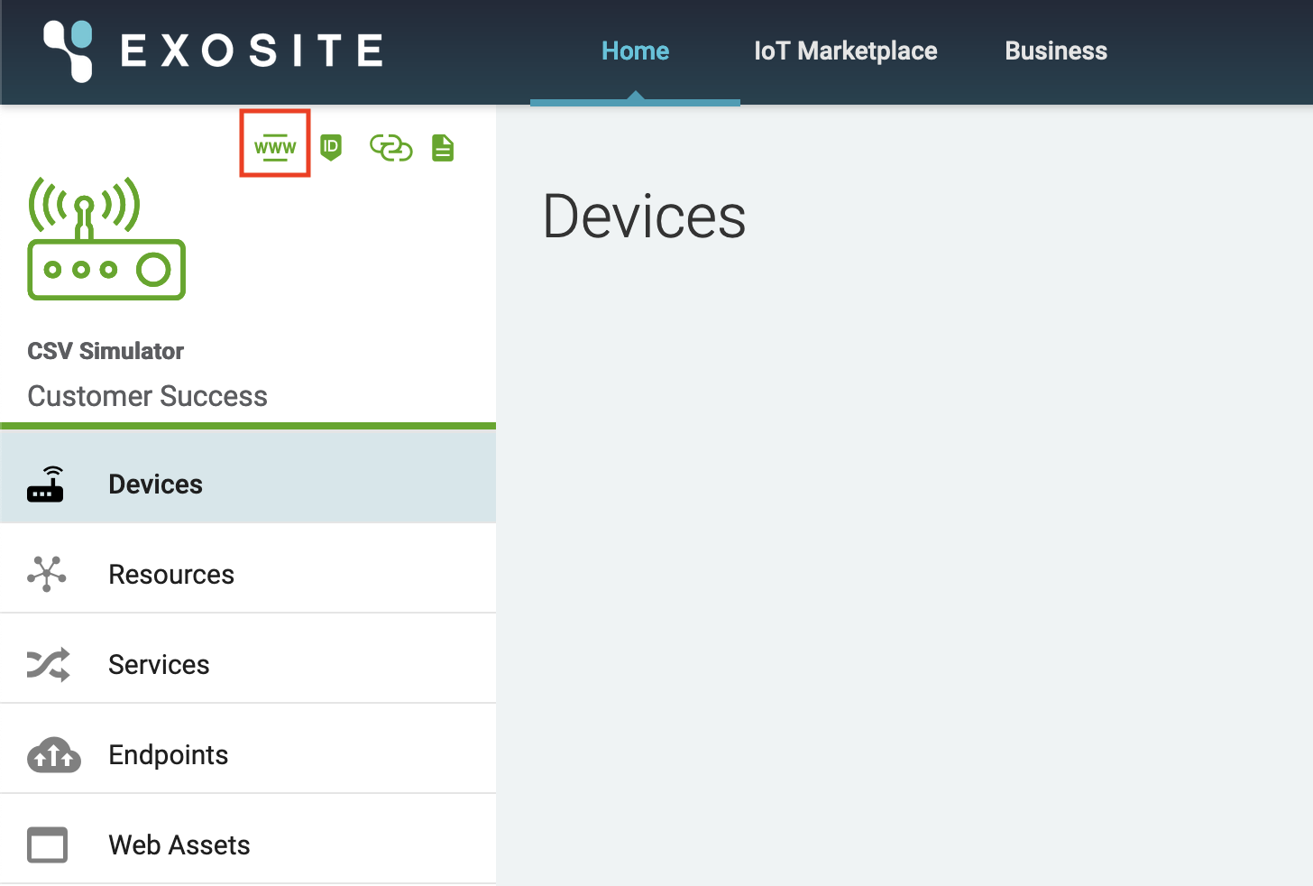
- Once the Simulator is enabled you will be brought back to your Murano instance homepage. Scroll down and find the connector that you just named and click on the name to open the overview of the newly created connector.
- From here, click on the WWW icon to go to the simulator setup.
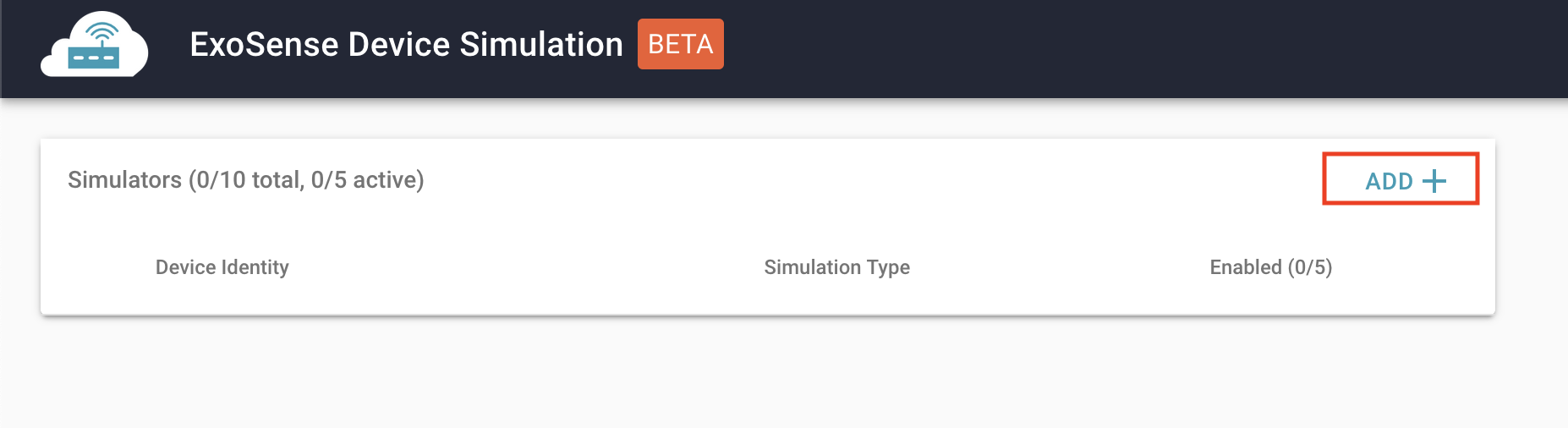
- Click + Add to create a new device.
- Give your device a name and select CSV as the simulator type. Click Create to create the device.
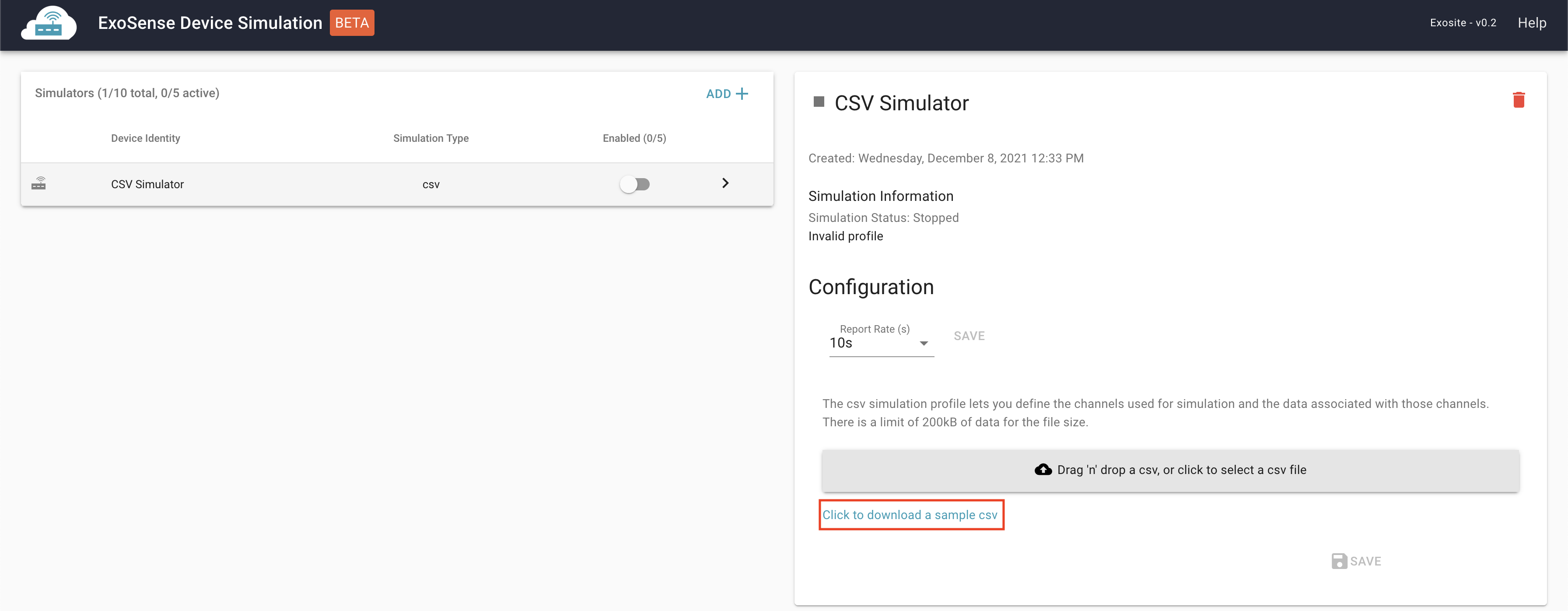
- Click on your newly created device to expand the configuration window for the simulator. Click on Click to download a sample CSV.

Setting up the CSV for the Simulator
Once you have the sample CSV for the simulator downloaded, open the file and you will be presented with a CSV that has 3 channels: temperature, humidity, and pressure. These can be left or they can be entirely changed if you do not want to include them in your simulator.
The steps below will cover how to add additional channels into the simulator. When adding additional channels, please refer to our Data Schema documentation for accepted data types and data units, found here: Schema - ExoSense Data Type - Exosite Documentation
- Upon first opening the CSV, you will see 4 columns. The first column, containing rows
id,display_name,properties.data_unit,properties.data_type, anddatashould remain untouched. These are crucial to the simulator running properly. - The
idrow is the ID of the channel - for channel IDs that contain multiple words we recommend underscores (i.e.oil_pressure). Feel free to add as many channels as you would like simulated. - The
display_namewill be the name shown in ExoSense for the signal once it is added to an asset. This can contain spaces (i.e.Oil Pressure). - The
properties.data_unitrow is the unit that this channel will be reporting. This will need to follow our data schema. - The
properties.data_typerow is the data type that you would like the channel to report. Again, this will need to follow our data schema to work properly. - The
datarow is the start of the data for the channels. The simulator will run through these rows from top to bottom, restarting when it reaches the bottom.
You may add any number of rows to the bottom of the CSV for the simulator to run through. If a data cell is empty, the simulator will not ignore it and it will send through a blank/null data point for the channel(s) that do not have data.
I have created a new channel current_draw in the example below:

From CSV to ExoSense
Once you have your CSV completed with the desired channels and channel data, our next steps are to upload the CSV to the simulator, enable the simulator, and get the data to show in ExoSense. The steps below will walk through this process.
- Above the link where you downloaded the CSV, click on the button to upload your newly created CSV file. Once uploaded, you should see the channels you created populate.
- Once the file is uploaded, you can change the report rate if you’d like. The default is 10 seconds, meaning that every 10 seconds the next row of data will be reported for all channels in the CSV.
- Once the report rate is set how you would like, click on the toggle switch to enable the simulator.
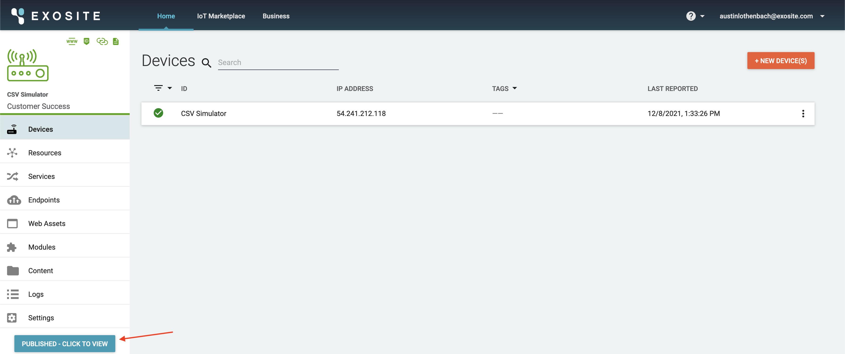
- Back on the Connector overview page now, you will see the simulated device under the devices section. Now we need to connect this connector to your ExoSense instance. To do this, click on Published - Click To View in the bottom left:
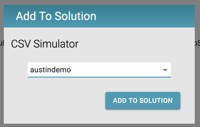
- Click on the orange Add To Solution button and select your ExoSense instance from the list and click on the Add To Solution button to confirm.

Once the simulator is added to your ExoSense instance we will want to login to your ExoSense instance and create an asset for the simulator.
In ExoSense
- Click on Devices on the left-hand side of the screen, then click on Unused Devices at the top. You should see your newly created simulated device in this list. Click on the checkbox for the device and in the top right, select the group to place this device (generally Home), and click on Assign to Group.
- Once the device is added to a group, it will move from the Unused Devices section to the Devices Section. Find the device in the Devices section and click on it to view the overview of the device. You will see the Overview, Channels, and Log tabs.
- From the Overview tab, click on Create Asset From Device. Give your asset a name, assign it to a group (if necessary), and edit the icon if you’d like. Once you are done, click Create in the bottom right.
- Once the asset has been created, you will be brought to the overview that shows the signals on the asset. To start creating dashboards, click on the View Asset Dashboard icon in the top right to be brought to a blank dashboard.
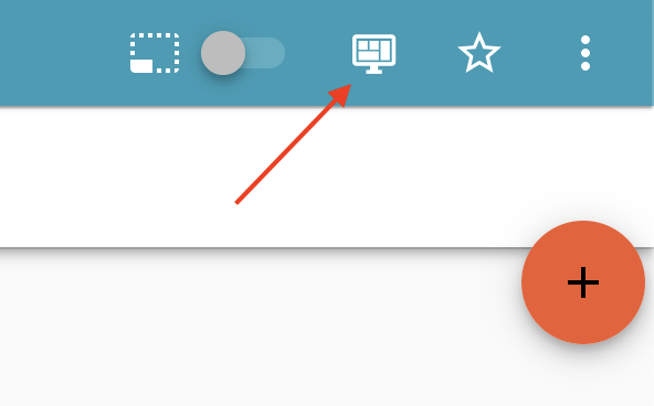
- From the Dashboard, click on the + button in the top right to begin adding panels to display the signal data on your dashboard.
- Done!

For additional help with creating dashboards and adding panels to your dashboard, please refer to our documentation here: Dashboard Overview - Exosite Documentation
If you run into any difficulties with the simulator or any steps in this guide, please feel free to reach out to Exosite Support at support@exosite.com.